Inverted V Scan For Analog Flight Displays
The Attitude Indicator (AI) is the most critical instrument for maintaining aircraft control when outside visibility is restricted. No matter what circumstances a pilot may face—turbulence, distractions, disorientation, or emergencies—establishing a stable flight condition by keeping the wings level on the attitude indicator will prevent things from worsening and avert a dangerous stall/spin sequence. It is the only aircraft instrument that can be “stared at” for long periods of time without serious negative repercussions. In a moment of panic or confusion, staring at the attitude indicator to maintain aircraft control and buy some time to think through what to do next is far superior to allowing your eyes to flitter around the cockpit making superficial glances at other instruments without registering any real meaning from them. The AI is by far the simplest and most intuitive instrument in the panel, and it should always be home base.
The attitude indicator is so critical to instrument flight that even experienced pilots have lost control of their aircraft when it fails. For this reason, many IFR-equipped aircraft (such as those with electronic flight displays) have a back up attitude indicator with a separate power source. But even aircraft that only have the standard six-pack of analog instruments can still be flown in a stable, wings-level manner when the attitude indicator fails as long as the supporting instruments are properly utilized.
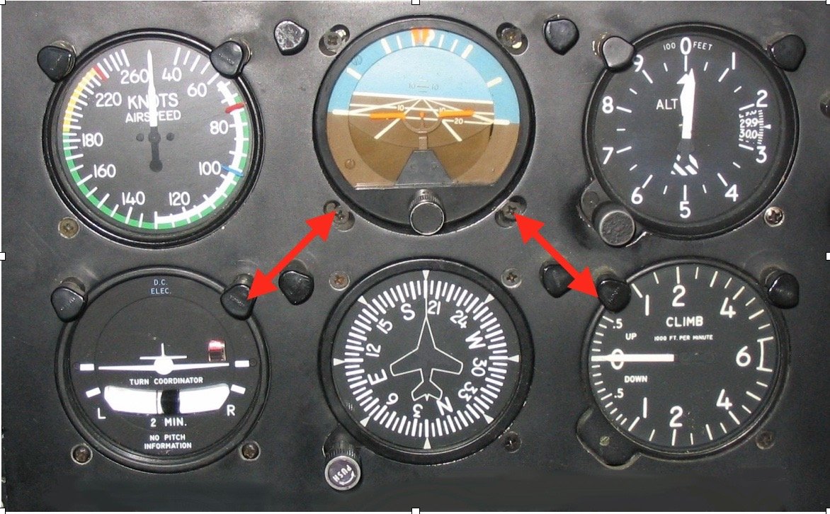
The Inverted-V is a simple scanning technique that incorporates the Turn Coordinator (TC) and Vertical Speed Indicator (VSI) to back up the information being displayed on the Attitude Indicator (AI). The TC shows the trend and rate of turn, rate of roll, and rudder coordination. The VSI shows the trend and rate of vertical movement. The sequence of the Inverted-V scan begins with the AI then moves to the TC, then back to the AI, then to the VSI, then back to the AI where the sequence repeats. This technique has been called the “music scan” because it follows a simple 1 and 2 and 1 and 2 pattern, with the AI representing the “and”:
and (AI)… 1 (TC)…and (AI)…2 (VSI)…and (AI)…1 (TC)…and (AI)…2 (VSI)…and (AI)…
If the AI fails, this scan continues in the same manner, using the information from TC to construct an imaginary image of an attitude indicator in the brain that is consistent with the turn coordinator. Following the sequence, the eyes then move to the VSI to obtain the necessary information to refine the imaginary image of the AI so that it shows proper pitch. The pilot can now employ this mental image as a reference for utilizing the flight controls.
The Inverted-V scan also makes it possible to quickly recognize instrument or system failures.
The AI is a pitch and bank instrument powered by the vacuum system. The TC is a bank instrument powered by the electrical system. The VSI is a pitch instrument powered by the static air system.
If there is a difference between the AI and the TC, the discrepancy must be resolved by looking at a third bank instrument—the Magnetic Compass (MC), which is powered by the earth’s magnetic field (the Heading Indicator should not be used since it is also powered by the vacuum system). The bank instrument that differs from the other two is malfunctioning or the system that powers it has failed. For example, if the AI shows a left bank but the TC and the MC both show a right turn (the numbers are getting bigger), the AI or the vacuum system has failed; but if the MC shows a left turn, the TC has failed. Similarly, if there is a difference between the AI and the VSI, the difference should be resolved by looking at a third pitch instrument—the Altimeter. If the AI and the Altimeter both show a climb, but the VSI shows a descent, the VSI has failed. However, if the AI shows a climb but the VSI and Altimeter both show a descent, the AI may still be correct. There may have been a failure of the static system that powers both the VSI and the Altimeter. The only way to be sure will be to activate the alternate static system (or break the glass face of the VSI to create your own alternate static system). Then the discrepancy can be resolved by identifying the failed pitch instrument as the one that differs from the other two.

